W6SI Blog Page (Entry 9)
4/15/2017
HF Band J-Pole Antenna (or NOT!)
Continuing on J-Pole antenna saga.
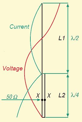 J-Pole Antenna Schematic (courtesy: wireman j-pole DK7ZB) |
Despite the long history and popularity of this antenna, there seem to be a lot of confusion about what this is and how it works. For example, confuses this antenna with Zepp antenna, an end-fed wire antenna, which J-pole may have its conceptual origin but they are not the same thing. One of the big debatea about this antenna is whether to ground it through the support mast, or isolate it. After some studying on the subject, I personally conclude this: “It doesn’t matter”. As I mentioned in the last blog (“V.UHF Dual Band J-Pole Antenna”), J-Pole is a half wave vertical dipole with stub match at the bottom. The Total length of the stub is about 1/4 wave length, and the bottom is the low impedance (virtual 0v) point. There is no current flowing in/out of there if anything is connected. The coax feed line connects to it slightly above the bend, locating the point where the impedance is about 50 ohm. Hence the “bottom” of the stub is a neutral point, it really doesn’t matter if you ground it or not. CAUTION! As with many of my writings, I'm talking in practicality. Above explanation is true as far as idealistic case is concerned. Alas, nothing is ideal in this world. There is always some factors creeping in to break that balance, so you can expect some current flowing through the bottom of the stub to the support mast (assuming it's metal). Depending on magnitude of the leak, it's almost as bad as common mode current in the outer conductor of the coax feedline. Fortunately, when you talk about 2m / 440 antenna, this imbalance can be expected to be small and hence it doesn't matter for most cases. IMHO, that is. |
There are some argument for grounding the antenna, if nothing other than lightening hit immunity. Even though J-Pole is a "ground independent" antenna, it is often a good idea to ground it, to give a good reference point, to identify where the feedline ends and where the antenna begins. When you have a matching problem and SWR does not go down to usable level (im my definition, less than 2.0:1), it is often useful to ground the antenna at balance point, and that alone might solve the problem.
Of course, if you have lader line construct antenna (like DBJ-1) and mounted on non-conductive mast, then there is no need to ground it.
But! As I mentioned in the last installment, please do insert an RF choke at the feed point. It practically gives the same effect as grounding the mast.
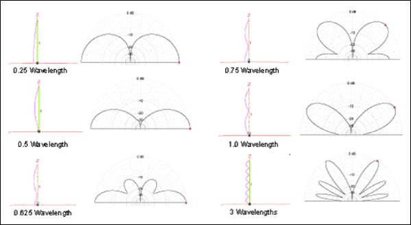
Radiation angles of various vertical radiation elements
Now, that is not the main subject of this blog entry. One endearing property of J-Pole is that it is a half wave dipole, independent of the ground. One of the popular DX antenna for not-so-fortunate bunch of us who cannot raise a sky high tower with a big beam antenna, is of course vertical. More precisely, vertical monopole. Most of them are of ¼ wave variety, relying on the mirror image under the ground, which is typically not so perfect. So its efficiency depends on the grounding system (can you say, “radials”?) But it has a nice low angle of radiation.
Enter J-Pole. Its radiation element is ½ wave, i.e., twice as long, and its current maxima, the maximum radiation point is half way up from the ground. See the diagram on the left. The radiation angle is yet lower than ¼ wave monopole. And allegedly, it is less prone to man-made noise which tends to loiter around near ground level. It does not rely on the quality of the soil on which it stands (well,not in terms of radiation efficiency. The ground reflection helps, though. But that's another subject).
You might also notice that longer antenna, 3/4 wave and 1 wave length etc. actually have substantial portion of power radiated to unwated higher angle.
Longer is not necessarily better, folks.
So how about it? For the size of 40 meter 1/4 wave monopole, why not building a 20 meter J-Pole?
Alas, it does have some shortcomings.
First, the stub matching required to feed it from the bottom, the voltage maxima (don’t ever touch that element bottom, especially when high power is being transmitted). That also makes the antenna substantially longer. About 50% longer. That’s not so good for us living in the ariel-restricted land.
40meter ¼ wave monopole is about 10meter tall. 20meter ½ wave J-Pole is more like 15m tall and the bottom part is a high voltage hazzard.
Now I found a few discussion on the net about pulling the gamma match in the horizontal direction to avoid the extra height, but I wasn’t crazy about pulling around a wire with potentially harmful voltage on it near ground level.
Second, this is inherently a single band antenna. You can pull some tricks like 2 band version I discussed in the Blog #8, but it’ll be a “single band antenna that can be made to work on other bands too”. Design and construction of multi-band HF version would be complicated. May not be so desirable.
Why am I thinking about something like this, such a foolhardy idea of raising HF band J-Pole?
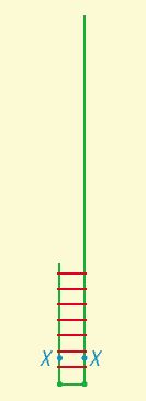 |
The classic J-Pole with both sections mounted vertically. Length 3/4-lambda. For 20 meter band, 1/2 lambda radiator is 9.98m, stub section is 4.73m each. So the overall height of the antena will be ~15 meter (45 feet) |
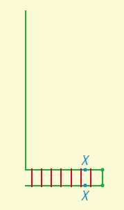 |
It is no difference in the radiating conditions, if the 1/4 lambda-part is vertical or horizontal. The pattern should identical with a vertical dipole. But be careful part of the stub can be a high voltage hazzard. |
Because my Mission Viejo Special multi-band vertical is out there for a few years now, and in badly need of a major maintenance. I can rebuild the same antenna, or I can try the “Mark 2” version!
My main band of operation is 20meter, but I do come in and out on other bands too. So that’s a vote against J-Pole. It was fun thinking about it…
Now, the other popular version of vertical antenna is the famous 43-foot metal tubing that is not resonant on any interesting frequency. They are still more or less configured monopole, so requires ground system, but that’s OK. I already got them.
One reason I do not care for that type of antenna is that its length prefers low band 80/40 and maybe 20 meter (160 meter, well OK but it’s a stretch) but not so great for 17 meter and above. See the radiation angle diagram above. The element is simply too long and much of the radiated energy is wasted warming the local sky.
True, the sky weather these days are not so hot, so why worry about high bands? I guess it’s just my nature.
So my idea of this “MV Special Mark 2” is to raise a monopole a bit longer than ¼ wave 40 meter vertical (so it is “almost” ½ wave for 20 meter), but not particularly resonant on any ham band frequencies. Let the antenna coupler do the job. I already have one I use for MV Special. By avoiding resonance, I avoid the voltage maxima at the feed point like J-Pole. It's still high, but not as much, and the feedpoint impedance is not as high, so it is easier for the coupler to tune.
That still leaves the element too long for 15 meter and above. One reason I am wary of simply adding parallel radiation element is that in this scheme, none of the element is resonant for any ham band, by driving the coupler, there will be multiple "match points", and there is no telling how the antenna is tuned, mostly depending on where I was before. So I still have to do some
more thinking.
Note I said “coupler”, not “tuner” which commonly refers to a tuner box in the shack next to the transmitter, or even embedded in the transmitter. I’m talking about one right at the feed point of an antenna. That’s a coupler. One redeeming property of that distinction is that coupled system will not allow common mode current to flow on the outer skin of the feeding coax line. I simply don’t care for the hot cable.
One obvious question. The feed point impedance can vary wide range (a few tens of ohm to several kohm), depending on the band I am interested in. Can a coupler tune to all bands? Well, answer is to augment the tuning range by use of impedance transformer. Also known as “n:1 balun”. Really is an Unun.
People like Palomer Engineers sells something like that, but can be costly. I got some toroids in stock. Why not build one to see if I can do it?
(to be continued…)
Above is a reflection of my thought and only mine. But if you have any questions, feedback and/or suggestions, please send me an e-mail. I might reply on this page (sorry, no guarantee)
| Home Page | Blog Index | Next Blog Entry |