Mission Viejo Special, The Multiband Vertical (#2 of 6)
Specification
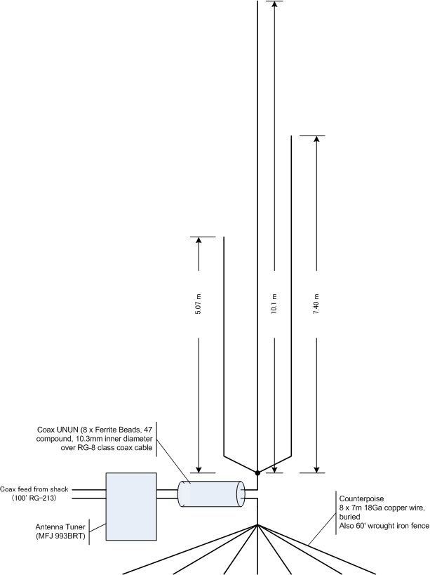
The antenna is a vertical, with three different radiation elements, parallel to each other. It functions with less than 2.0 SWR for most of the bands for 40, 30, 20, 15, 10 and 6 meter bands without antenna tuner, as one of three wires are ¼ wave length or odd multiples thereof. And it functions as 5/8 wave length ground plane for 17 and 12 meter bands. You will need a tuner for those bands, but like those VHF/UHF antenna of 5/8 lambda, you can expect a theoretical gain of near 3dBd, due to boost on the low angle of radiation.
Theory
There is nothing revolutionary about this antenna. The three wires are cut ¼ wave length of 7.1MHz, 10.1MHz and 14.15MHz. See the table below.The base 40 meter element, whose background is painted blue, will also work for 17 and 15 meter bands. 30 meter element, painted purple, also works for 12, 10 and 6 meter bands.
Table 1: Theoretical length of wire element (meter) for given frequencies
freq(MHz) |
l |
l / 4 l |
5/8 l |
3/4 l |
5/4 l |
Need Tuner? |
7.1 |
40.41m |
10.10m |
25.26m |
30.31m |
50.52m |
No |
10.1 |
28.41m |
7.10m |
17.76m |
21.31m |
35.51m |
No |
14.15 |
20.28m |
5.07m |
12.67m |
15.21m |
25.35m |
No |
18.1 |
15.85m |
3.96m |
9.91m |
11.89m |
19.82m |
Yes |
21.2 |
13.53m |
3.38m |
8.46m |
10.15m |
16.92m |
No |
24.9 |
11.52m |
2.88m |
7.20m |
8.64m |
14.40m |
Yes |
28.5 |
10.07m |
2.52m |
6.29m |
7.55m |
12.58m |
No |
50.5 |
5.68m |
1.42m |
3.55m |
4.26m |
7.10m |
No |
Most of you know that an odd multiple of ¼ wave length wire resonates at low feed point impedance, but Interesting thing about this table is that 40 meter element is also nearly 5/8 l for 18.1MHz, in addition to resonating ¾ l for 21.2MHz.
Similarly, 30 meter element, which is actually cut little longer to resonate at near 10.0MHz, is also near 5/8 l of 24.9MHz, and almost 5/4 l for 50.5MHz, on top of ¾ l for 30MHz. This element was actually cut for ¾ l length of 28.5MHz, which is a bit too long for 30 meter band, but as it is shown in the SWR chart later in this document, it came out passable.
20 meter element (orange) is only useful for 20 meter band.
Of course, while impedance match is one thing, radiation effectiveness is quite another. The radiation pattern of vertical antenna is ideal at wire length of ½ l (albeit wrong impedance at the bottom). Much longer than that, due to the extra current lobes on the radiation element, significant part of the radiation shoots up higher, only to burn the local cloud. ¾ l is the practical limit for DX application. Therefore, 6 meter band, on this antenna, is workable but not really ideal for DX-ing. It is more suitable for local rag-chewing.
5/8 l is an interesting case, where the wee bit extra radiator over ½ wave length produces a small current lobe that actually pushes the main lobe down to force a lower radiation angle. This is how those VHF/UHF ground plane antenna achieves omnidirectional gain, and the same mechanism is applicable here. But because at this wavelength, antenna is not resonant and feed point impedance is moderately high and complex. So it requires an impedance matching scheme. I am using an antenna tuner at the base (feed point) for these bands. It must be done at or near the feed point, since tuning in the shack through a length of coax cable, you will have no idea how it looks like at the feedpoint of the antenna.
| Ü | Introduction | Þ | |
| Specification | |||
| Theory | |||
| Mast, Base | Radial Plate | Boom | Elements |
| Grounding | UNUN | Tuner | Adjustment |
| On The Air | |||