| |
“Magnetic Loop Antenna”

Chapter 2: How does a Magnetic Loop work?
|
|
| |
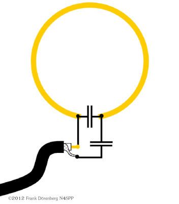
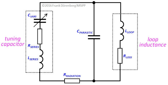 Equivalent Circuit Diagram of a Magnetic Loop Antenna Equivalent Circuit Diagram of a Magnetic Loop Antenna
(source: https://www.nonstopsystems.com/radio/frank_radio_antenna_magloop.htm)
©2012 Frank Doerenberg N4SPP, used with permission
|
In the last chapter, we talked about antenna as a media converter between transmitter RF power and the air, or an empty space. We talked about electromagnetic field and how an antenna can be electric, or magnetic types. And why magnetic is a good thing.
Well, is there any drawback for being magnetic?
For one thing, it is a difficult antenna to build. And there are several operational requirements not typical of other e-field type antennas. To understand what I mean, let’s talk a little bit about how a magnetic loop is constructed in practice.
|
Electrical Facts:
Look at the diagram above. A loop antenna works like an LC resonant circuit. The loop is the inductive element. You insert a tuning capacitor at the top (left side of the diagram) to tune. Just like you tune an old-fashioned radio. This is so because the entire structure of the magnetic loop is so small compared to the wavelength of the signal you are dealing with, unlike dipole and/or other e-field type antennas. Simple enough, right?
Well, here are some numerical facts (presented here without complicated calculations):
A loop of 1m diameter has radiation impedance of about 0.1 + j300 ohm for 14MHz. For 100 Watt input, about 31.6 Amp of RF current is flowing through the element, and the voltage between the capacitor gap is about 4.5KV.
TUNING:
Aside from “Don’t touch that antenna while transmitting!” , here’s what you need to know:
- The loop element must have the absolutely lowest resistance.
At 0.1 ohm radiation resistance, even 1 ohm resistance in the path can eat up more than 90% of your transmit power.
A small loop of 1 meter diameter with a wire element (say 2mm diameter) have series resistance ~0.06 ohm, some 60 times greater than an aluminum tubing of 20mm diameter, making them substantially less efficient.
- The capacitor must be of very high Q (that is, low resistance loss) and of very high voltage tolerant.
For the above example of 1m diameter loop, for 14MHz, it takes about 60pF of capacitance to tune.
A few different types of capacitors are used for the application. The "normal" types of capacitors we use on PCB's are largely not usable here due to problems like (a) volrage tolerance, (b) Quality factor, high frequency characteristics in particular, (c) heat dispersal and (d) capacitance value stability, etc., etc.
- Air variable capacitor
The most conventional type of variable capacitor, but big and bulky. The one shown in the picture is, as big as it may look (188mm x 77mm x 77mm), is only 200pF 3.5KV. And it is severely affected by elements. Old receiver capacitors from vacuum tube days are reasonably small, but do not take much more than 100V. Transmission capacitors, like MFJ’s loop antenna use this type of capacitor housed in plastic casing. But IMHO, the longevity of itsw seal can be a problem.
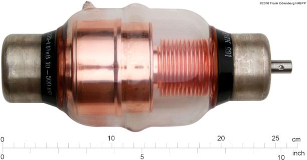
- Vacuum capacitor
This is the capacitor of choice by DIY builders of magnetic loops. It has high voltage tolerance, good capacitance and precision tuning mechanism. The pictured one is about 500pF, 10KV. Good and sturdy, but a bit fragile. Not small (the pictured one is about 25cm long). An adjustment mechanism must be provided ad-lib. And EXPENSIVE (> $200), if you can find one. It doesn’t appreciate being out in the element, so if your antenna is an outside permanent installation, you will need to house it in a good casing.
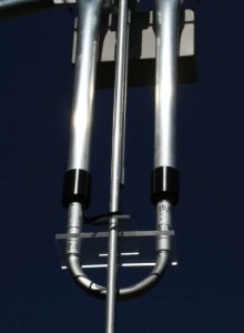
- Trombone capacitor
This is a nice compromise capacitor for this application. I found this in the loop antennas built by a Japanese craftsman. The inner tubing slide in and out of outer tubing, just like a music instrument (thus its name). It is relatively small and light, and reasonably weather resistant. Capacitance is not very large ~25pF, but it takes a high voltage (6KV). The antenna uses extra boxed capacitor to compensate for the small cap.
- Coax Capacitor
This is a poor man’s high voltage tolerant capacitor, where you use the capacitance between inner and outer conductor of a piece of coax cable. The capacitance is not very big per length, and not variable. So by itself, not useful for moving around the frequencies. It tolerates maybe up to 1KV, which may be good for 10 ~ 50 Watt. A few of them in parallel may make it usable for a capacitance booster for trombone capacitor whose capacitance is not very big, to afford moving to a lower band.
|
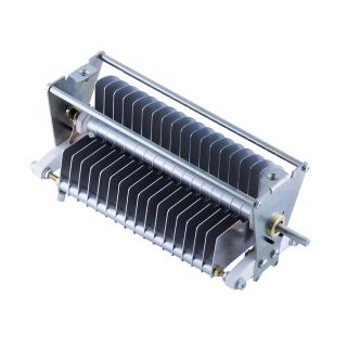  
From left to right: Air Variable Capacitor (source: http://variableaircapacitor.com/air-variable-capacitor-25-200 )
Vacuum Capacitor (source: https://www.nonstopsystems.com/radio/frank_radio_antenna_magloop.htm N4SPP),
Trombone Capacitor
|
As a high Q circuit, the tuning is very critical. That means this type of antenna is always very narrow banded. SWR 2.0 – 2.0 bandwidth is usually less than 10KHz. It degrades very rapidly outside of that.
And its high voltage tolerance requirement can make the physical size of the capacitor big, unless you limit the power level. The small, light loop antenna like Alex Loop are using smaller air variable capacitor, hence its power handling limit is low (~10 watt at most).
MATCHING
So now you know the efficiency of a loop and you can tune it to a specific frequency. What else do you need?
As I have told you that the impedance of this type of antenna can be as low as 0.1 ohm. If you would like to feed it with a 50 ohm cable (you would), then some kind of impedance match is required.
By varying the tuning capacitance, it can be tuned to a wide range of frequency, but impedance match can be tricky. |
 (source: http://www.i1wqrlinkradio.com/antype/ch9/chiave151.htm) (source: http://www.i1wqrlinkradio.com/antype/ch9/chiave151.htm)
|
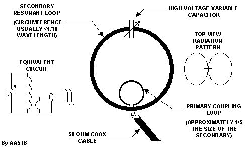
A typical way to couple the transmit power to the loop antenna is through an un-tuned coupling loop. This is like an RF transformer, with the air as its dielectric. A loop of wire (typically a coax cable) is tied to the feed line, and placed near the loop element. Feed impedance can be adjusted by making the coupling “tight” or “loose”, basically a measure of how closely parallel the coupling loop is to the element (See images below)
Advantage of this technique is that by changing the shape of the coupling loop, a wide range of impedance match can be made, across many different bands.
The match point (shape?) may be fairly constant across a band, unlike tuning capacitor that needs adjustment every few KHz. But you still has to change it from one band to another.
If the technique has a weakness, it is more a manual process, and automating it can be difficult.
|
"Tight" Coupling and "Loose" Coupling using un-tuned coupling loop |
|
Another approach is a “tuned” coupling technique, where the impedance is matched using the ratio of tuned capacitor to the series capacitance on the feedline. This makes it unnecessary to tamper with the shape of the coupling loop for tuning, but you’ll have to tune two capacitors independently to obtain resonance and the match. Considering the narrow bandwidth of a small loop, this approach can double the cumbersomeness of already inconvenient loop operation. |
Tuned Coupling
(source: https://www.nonstopsystems.com/radio/frank_radio_antenna_magloop.htm)
©2012 Frank Doerenberg N4SPP, used with permission |
The third approach is Gamma match. The same technique typically used to match the impedance of Yagi beam antenna. A proper “tap point” is sought to match the impedance of the part of the radiating loop element. The diagram on the right shows one such example. Since the dimension is a function of the loop length and the wave length, implementation and usage of this technique across different frequency bands is not straightforward and can be very complex and it may requie frequent re-tuning.
It has been done by a few manufacturers and DIY amateurs, however. |
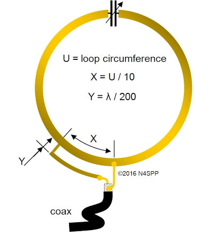
Gamma Match
(source: https://www.nonstopsystems.com/radio/frank_radio_antenna_magloop.htm)
©2012 Frank Doerenberg N4SPP, used with permission
|
SUMMARY THIS CHAPTER
So what have we learned about the construction of a magnetic loop and its usage?
- Loop antenna can be built to tune to just about any frequency you desire, almost independent of its surroundings.
- Depending on how it is constructed, what components are used, a loop antenna can be light, low power and inexpensive, heavy, high power and expensive, or somewhere in-between. There are trade-offs to be made.
In other words, a loop antenna is simple in terms of its operation theory, but it can be a difficult antenna to build, both mechanically and electrically, and there are many trade-offs to consider.
- Use a high voltage capacitor, or limit your transmit power
- Be extremely cautious about NOT injecting lossy resistance in the element
- The impedance match can be tricky
- Because it is narrow-banded by nature, it is necessary to devise a way to re-tune the antenna for every little shift in the transmit frequency (and it is not done by an antenna tuner in your transmitter).
|
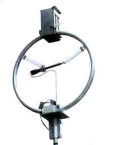
I3VHF "Baby Loop" Antenna utilizes Gamma match.
Note the complicated actuator arm for the match and
the large capacitor casing. |
It took a lot of explanation, but now the short answer to the question at the top.
Is there any drawback for being magnetic?
Yes, the antenna is difficult to construct, and has many trade-offs to be made. Even if you are buying a manufactured product, it is extremely important about those trade-offs. There also are additional operational requirements such as frequent re-tuning, due to its characteristic narrow banded-ness.
So much for the theory, how does a magnetic loop work in real-life?
That will be the subject of the next installment.
Questions, comments, opinions, etc. all e-mail to me
To be Continued... |
|
| |
| |
|
|