| |
“Magnetic Loop Antenna”

Chapter 3: Practical Aspect of Magnetic Loop Antenna
|
|
| |
I hope the past two installment of this writing gave you clearer idea of what this mysterious antenna is all about, and where those mystic quality came from. Though some qualities are overstated (no, it does not outperform beam antennas, and does not miraculously solve all antenna problems), but this little antenna is for REAL.
To summarize its characteristics we covered so far:
- Magnetic Loop antenna is small; its total length stays 0.1 lambda or less
- It acts like an LC resonator, and with a tuning capacitor, it can be tuned to any frequency in most environment.
- Due to its high-Q nature, the bandwidth of the tune is necessarily narrow (typically ~10KHz)
- When receiving, because it primarily senses magnetic field instead of electrical field in near field (i.e., 1 lambda radius), it is immune from E-field noises of nearby sources.
- Once outside of near-field region, it acts the same as any E-field antennas.
I also mentioned that during the transmission, the loop flows a large RF current around its element, and develops a high voltage across the gap (where the tuning capacitor goes). Beware.
And if you recall in the last installment, I mentioned but not elaborated on transmission advantages of magnetic antenna. So that’s where we start this installment.
Historically, it has been mentioned that MLA works better when there are conductive surfaces around. There are many stories and write-ups about it, but I have not found any scientific analysis and/or in-depth study on the subject. Until now, that is. |
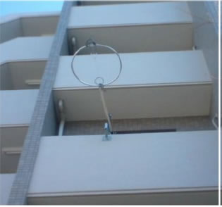
Loop Antenna at JF1VNR
(Veranda at a high rise condominium)
|
JF1VNR lives in a high rise condo in Yokohama Japan, and uses an MLA sticking out from his veranda. Like most operators he kept his antenna stick out as far out as possible to keep distance from the building. But when the wind forced the loop closer to the building, he noticed that he actually could make more DX contacts.
Apparently, the secondary radiation due to induced currents in the steel rod structure of the building interfered constructively with the MLA radiation, for a better performance than MLA alone. Much like a two element beam.
He used E-field simulator XFdtd to simulate the phenomena by building a model that includes the building structure as well as the MLA antenna. It predicted when the antenna is about 70cm away from the front of the building, the radiation efficiency improved to 56% (from 34% with MLA alone) on 20 meter band. According to the analysis of Dr. Kogure, JG1UNE, when the grid of the steel rod is wide enough, the current profile similar to ½ lambda dipole is induced on those steel rods to boost the transmission radiation. The lower picture is an output from another E-field simulator Sonnet showing the surface current distribution (note the MLA in middle front, depicted as a rectangular loop). |
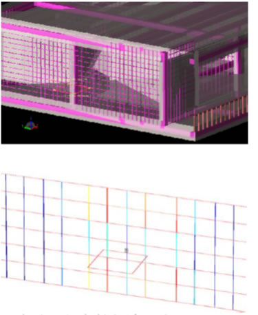
(Top) XFdtd plot of E-field around MLA in veranda
(Bottom) Sonnet plot of induced current in struactural steel rod
Courtesy: MLA-48 Project Newsletter Vol 7
|
High induced current is indicated by red color, and blue means less current. You can see the strong currents in horizontal direction.
Basically, those gentlemen observed the phenomenon, analyzed and painstakingly built a mathematical model, simulated to match the observation. Fantastic.
So this “myth” is no longer a myth, but the real, repeatable physical situation.
These two, along with my loop antenna craftsman JA1QOJ, are the founders of MLA enthusiasts group called MLA-48 Project in Japan, who is dedicated to study, build and innovate all about MLA antennas. They are fascinating people and before I knew it, I ended up joining the group. More about them later.
To add my interpretation / extension of the finding, I guess you can use the surroundings favorably to form a kind of beam antenna using this tiny little loop. That is a very interesting mechanism and worth studying / experimenting more. It doesn’t have to be just on the veranda of high rise condo, you can place parasitic elements near the loop antenna to enhance gain and directionality of a loop antenna. In a small veranda or a tiny back yard. |
Deployment Strategy
With all the exciting features of MLA, it still is a cumbersome and/or limiting antenna to build and use. It deserves a serious thinking to deploy and operate. As represented by such as Alex Loop, many wire-based loop antenna are made for QRP or portable operations. That is an interesting subject by itself, but writing restricts the discussion to a base station set up, at 100 Watt power.
The key issues for the deployment include:
- Placement and surroundings
- Tuning strategy
- Safety and Maintenance
We’ll discuss them one at a time.
PLACEMENT of the antenna first deals with (i) sensitivity of neighbors and (ii) Owners Association. If you want a permanent set up, it is essential you keep a good neighborly relationship. It is beyond the scope of this writing about how you do that, but you know what I mean. One thing to know. Association can dictate what permanent “architectural objects” you can have in your property, but they have no say about your temporary set ups, like a basketball goal on wheels.
Another point about the placement, of course, how you can take advantage of the “surroundings” for the performance. Though I showed you the nearby conductive rods or surfaces can help you, it does not always work to your advantage. You need to experiment. As I always say, “an antenna project never ends”.
Of course, if you are setting up in a veranda or a terrace at your residence, you don’t have much choice on the matter. Pray for the best. If you are at a detached house, would it be better to place it on the ground with a tri-pod, or erect a mast on the upper floor terrace? Answer once again, is “it depends”. Experiment. In my past limited experience, it seems to work better when your loop is at or slightly above the roof. It is also noted that putting a loop on the top of a tall tower does not help. You are likely ended up with a sub-optimal antenna.
Another consideration. Since you have to tune repeatedly as you move around the band, your operating position needs to be close to the antenna (so you can manually adjust it) or have a mean to remotely tune it. Some store-sold loops have it, others don’t.
Which brings us to the TUNING STRATEGY. You can tune the antenna using carrier output from your transmitter and an SWR meter, but if you have to do this manually, there are safety concerns at multiple levels, even at a low power level.
Clearly, either an automated tuning or remote tuning is desired. Using a built-in tuner in your transmitter is not a good idea, because that tends to make your feed line coax a part of the antenna. It likely induces the common mode current on the outside skin of the coax cable, and that is bad news for any antenna. It is particularly worse news for Magnetic antenna, as the current-induced magnetic field will interfere with that generated by the loop, which is harmful. Hence every MLA should be fed with RF choke at the feed point, to avoid common mode current on the cable.
Automatic antenna coupler at or near the feed point is an interesting possibility, but nothing I know can tune down to 0.1 ohm radiation impedance of a loop antenna. If your tuner can actually tune it well, then it probably is an indication that there is so much parasitic resistance in the system, its efficiency is very low.
Clarification: “tuning” MLA antenna is a two-dimentional action; (i) resonance tuning and (ii) impedance matching. Since (ii) is fairly stable across band, above paragraph is describing (i), which has to be re-done every few KHz displacement.
SAFETY issue. First, you must stay sufficiently far from the antenna, to protect yourself from RF poisoning. FCC established a level of guidelines, but it never so specific about nearby MLA. The guideline I follow is for 20meter band at 10 Watt, you would want to stay clear by at least 2 meter (6.5 feet) and at 100Watt, 3 meter (10 feet), per some research report on the subject. Though considerably closer than I originally imagined, it is something to keep in mind when you are engaged in portable operation, as well as when your deployment calls for manual tuning.
Another issue, the high voltage and large RF current issue is addressed at the same time as the clearance rule above.
Though this may be a kind of extreme case, there is one more thing to note. If you are experimenting with this type of antenna, every contact, insulation, soldering, welding and hardware can be a source of parasitic resistance. With the antenna impedance as low as 0.1 ohm, every one of them can contribute to a significant loss of radiation efficiency. Not only that, the lost power is consumed in those areas. If the resistance is concentrated in a small region, transmission with as little as 100 Watt power can be a fire hazard. The construction of the antenna should be done with extreme caution, and it is helpful if you have a VNA (Vectored Network Analyzer) to measure any parasitic elements (NOTE parasitic resistance is not be measurable using a good old VOM tester). |
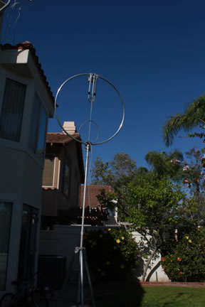
"Phase 1" deloyment of MLA at W6SI
One key feature of this deployment is the way I tune it. I did not want to transmit carrier every time I tune it, I placed a 2-port coax switch to split the antenna between the transceiver and the antenna analyzer. I use MFJ-226 an “almost VNA” for an antenna analyzer. It can plot SWR, complex impedance, return loss across a specified frequency range. A good value for its price. But any analyzer vector or scaler, can be used, but ability to plot across the range of frequency helps.
I switch the antenna over to the analyzer and plot the SWR curve. Then I use the remote to control the trombone to bring the match to the desired frequency. When I switch over the antenna to transceiver, it is ready to transmit at that frequency, and I didn’t disturb other stations on or near the frequency.
This set up was easy, cheap and effective, if not most convenient (unless you can explain to the family why the radio is sitting on the breakfast table).
The second phase is to move the set up to my upper floor terrace, and enable the operation from my radio room. I drilled a pair of holes on the wall to bring in the coax and remote cables, set up a pair of mast support to erect the telescoping fiber mast to support the antenna, that can be pushed up to the roof level. The base construction is completed, I am currently testing out the set up with the receiving loop antenna. I will follow up on this with the transmit loop later. |
Example Deployment
Here at W6Si station, I made a quick-and-dirty strategic deployment for trying out my MLA antenna. The antenna is acquired from Field Antenna of Japan. It is handcrafted by Munekazu, JA1QOJ. So far, he does not export his product outside of Japan, as production volume is extremely limited. So I went to his workshop and acquired one in person.
The antenna is a loop of 1.1 meter radius, of aluminum tubing of 22m diameter. The tuning is done with the combinations of Capacitor box (different box for each ham band) trombone capacitor, and Faraday loop coupling for impedance match. The trombone can be remotely adjusted with a simplistic controller to turn the motor. It covers from 40 meter to 10 meter bands. The loop is of single piece tubing, no welding or bolting. A very nicely built piece of hardware. And it is very light (a little more than 3 lbs).
I used a telescoping mast I had to support the antenna with the 5 foot tri-pod, also in my inventory. I placed it in my back yard, and raised it to about 9 feet level.
It is fed via 30 feet of RG-213 and the same length remote cable (a pair of 18-gauge unshielded wires) for the remote tuning. I set up my “research station” at the kitchen breakfast table, some 20 feet away from the antenna.
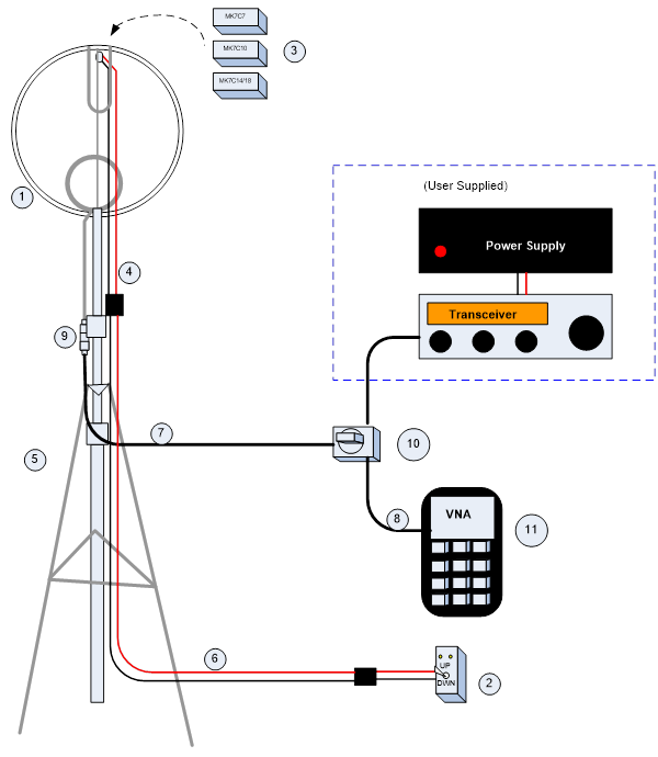
Legends: 1 - loop antenna, 2 - tuning remote, 3 - capacitor boxes, 4,6 - remote control cable, 5 - tripod, 7 -
feedline cable (RG213), 8 - short jumper cable, 9 - F/F adapter, 10 - 2 port coax switch, 11 - VNA (MFJ-226)
|
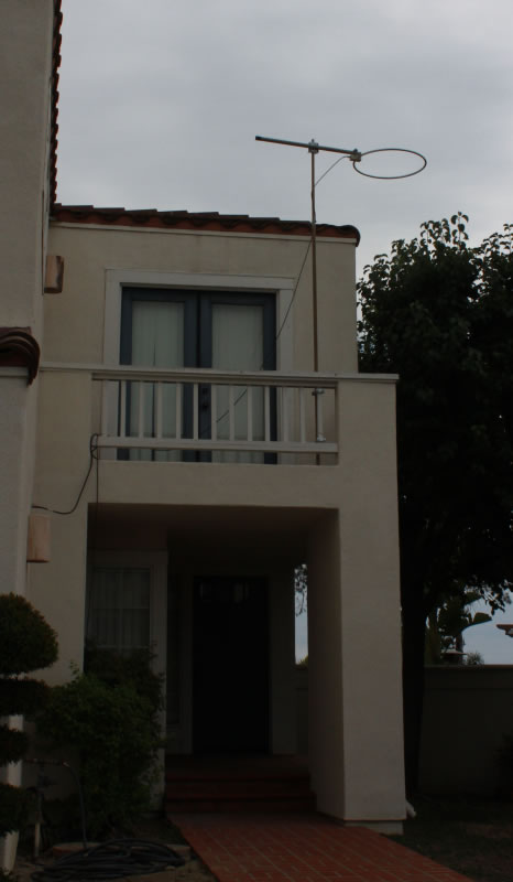
"Phase 2" Deployment of Loop Antenna
Note the horizontal orientation (omni-directional) of the loop.
|
The ultimate set up, which I do not yet have specifics, involve more sophisticated tuning method to make the antenna more frequency agile. While I was thinking about it, some new information is flowing in from the MLA-48 group that might redefine my long term strategy. Stay tuned.
We'll talk about it soon.
Observed Performance
So after all said and done, how well is it working?
Most unfortunately, I am doing this study when the DX condition is at worst. My beacon monitoring station is not hearing much of anything other than US, some Central and South America, Hawaii and New Zealand. All of Europe, Africa and Asia are missing. I do admit that the transmit efficiency of the antenna is less than brilliant, a legacy of a small radiator. It still is a match or better than many small antennas, but no match for full size dipole with good height.
So I am sorry to say there is not much I can report and brag when it comes to DX contacts. Oh well.
But I can tell you that it hears very well. WA6ED, Ed, tried out this antenna set up in his backyard for a week, and kept his JT65 station working. The screen shot shows it received and identified stations all over the world, though I am sure many of them are below 0dB SNR. He said it hears better than other antennas he uses. So it shows some potential. On the other hand, he only made a couple of domestic contacts two ways. So the transmission wasn't so great.
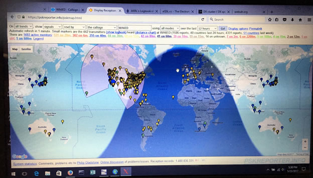
JT-65 screen shot. In one day, the loop received stations all over the world.
|
Resources
Not all of the information I present come from my own research & experiment. In fact (not surprisingly) most came from outside sources, which helped me learn the subject in relatively short time and still learning. Some of the most valuable information come from sources below.
With appreciation and gratitude, may I present:
N4SPP
Mr. Frank Doerenberg has one of the most comprehensive article on study and practical building of small Magnetic Loop antenna on line. I have used information on his site to build up my knowledge on this subject. Most informative and highly recommended.
https://www.nonstopsystems.com/radio/frank_radio_antenna_magloop.htm
AA5TB
Mr. Steve Yates publishes a lot of precious information about small loop antenna. Many are very useful and practical, with a good deal of theory behind it. And lots of useful links.
http://www.aa5tb.com/loop.html
…and not the least of it is his small loop calculator!
http://www.aa5tb.com/aa5tb_loop_v1.22a.xls
This is an Excel spreadsheet that by giving a size of the loop and target frequency, it can tell you all about that antenna.
MLA-48 Project
As I mentioned above, this is a Japanese group of scientists, engineers, builders and enthusiasts of small loop antennas. The group is led by Dr. Kogure / JG1UNE and Mr. Togoshi JF1VNR. The membership include engineers and hands-on experimenters that amassed amazing quality and volume of information on many aspects of the small antenna. Though many of it is not released publicly, and many of you can’t read them anyway, short of learning an arcane Asian language. since I joined the group recently, with a proper permission, I can “leak” some of the good information on this page (http://w6si.com).
VK5KLT
Since Australia has high concentration of population in the coastal area, the antenna space, apparently is hard to come by, so MLA is pretty popular. The paper published by Mr. Leigh Turner, VK5KLT is a very good thesis on the subject, and a must-read material for those interested. And you thought I was bullish about this antenna. Wait till you read this.
Download it from
http://www.ahars.com.au/uploads/1/3/9/8/13982788/article-antenna-mag-loop-2.pdf
CONCLUSION:
So I zipped through the basics of this well-known but little understood antenna in the three part write-ups. I hope that raised your understanding of the subject, and perhaps willing to experiment with it.
This is not the end. I shall continue to release more information on the subject, albeit irregularly.
Meanwhile, bring those comments, questions, suggestions to me: tak@w6si.com
To be Continued...
|
|
|
| |
| |
|
|
