| |
“Magnetic Loop Antenna”

Chapter 4: Automating Magnetic Loop Antenna (Part 1)
|
|
| |
So far, we have discussed the good and bad points of MLA. It is a small, easily set up (if somewhat hard to build), and surprisingly effective antenna. But due to its high Q in nature, the effective bandwidth is very narrow, not much more than 10~20KHz even at a relatively higher band. Frequent re-tuning is necessary whenever you change transmit frequency, and that’s often very inconvenient.
The loop antenna I have has a motorized trombone capacitor with a simplistic remote control to facilitate re-tuning without taking down the antenna. That still leaves a lot to be desired. |
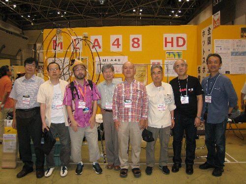
MLA-48 Members at Tokyo Ham Fest
|
MLA48
Recently in my trip to Japan, I had a fortune to meet a group of radio amateurs who are fanatically involved in studying, building and experimenting this type of small loop antennas. They call themselves MLA-48, and they are regular presence at Tokyo Hamfest, which is their Dayton counterpart. They are Phd’s, engineers, machinists, and veteran hams. Since many of them live in small high rise condos, it is no surprise that they are dedicated to build a small and effective antennas.
They showed me some loop antennas that are completely automated resonance and match controls. In fact the control unit won one of the top prizes at this year’s Hamfest homebrew contest.
Since we all share the same interest, I’d like to focus the next few installations about how they achieved that and how we can implement similar.. |
Resonance & Match
First, let us discuss what it means to “tune” the antenna.
For a small loop antenna to operate properly, it (a) has to be resonant to the transmit frequency, and (b) the feedline must be matched to the radiation impedance of the antenna. Both of those conditions must be met, in order to get your VSWR = 1. |
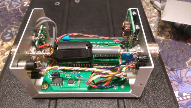
JR1OAO's "Super Tuner" for MLA
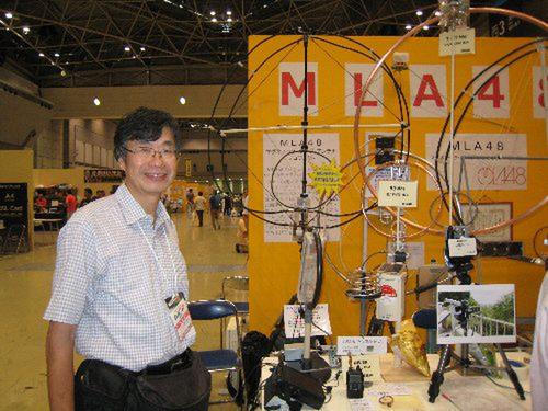
JR1OAO Nakajima OM
|
What does “resonance” mean? An antenna exhibits a specific impedance at its feed point. That is sometimes referred as “complex impedance”, as it has two components: resistance R and reactance X. Mathematically, it is expressed as Z = R + jX. (“j” is an imaginary number, the square root of -1. But that’s not important here). R does not change with frequency, but X does. So the complex impedance of the antenna feed point moves around as the transmission signal frequency moves around. Moreover, due to its “moving around”, there is a phase difference between voltage and current supplied by your transmitter. That phase error causes a complex load to bounce back part of the supplied power. When it is “resonant”, that is, X = 0 the impedance becomes pure resistance, and it can consume 100% of supplied power. In short, resonance is the act of removing frequency dependent reactance component from the complex impedance, Z = R
When you cut the wire to tune a dipole antenna, slide aluminum pipe in / out of beam antenna elements, and yes, tuning the capacitor of the mag loop antenna, they are all trying to achieve resonance.
For most E-field antennas, the resonance has a fairly good bandwidth, i.e., the reactance component stays low for a range of frequency, to cover the desired band. There are good and bad reasons for this, but we are not getting into that here. Small antennas, including Magnetic Loop antennas, on the other hand, generally have very narrow bandwidth, and every time you move transmit frequency by a few KHz, you will need to re-tune to re-achieve the resonance. And that cumbersomeness is one of the big reasons the antenna is not as popular at practical level as it should be.
|
Resonance
A typical resonance control is performed by a variable capacitor. If you managed to motorize the capacitor shaft rotation, and leave it to the tuning controller, it can be performed automatically. My loop antenna has trombone capacitor, which is already motor driven, using a toy motor. All I need to do is to supply +/- 3V of up to 100mA depending on the direction of rotation. However, since trombone capacitor range is limited (up to 25pF), additional capacitor box (selected for a specific band) is needed. For example, to resonate a 1 meter diameter loop antenna to 14MHz requires about 100pF capacitance.
If you use a vacuum capacitor that has range of 500pF or so, that can cover most HF bands and motor driven. That might require a substantially larger, stronger motor to drive.
And oh, do not forget: there is a very high RF voltage nearby. Insulation must be done properly.
So now you have achieved the resonance. Are you good to go now? |
Impedance Match
I wrote above that at resonance, the antenna “CAN consume 100% of supplied power”. That is, if the impedance at the feed point of the antenna equals the feedline cable (50ohm). This is like you fill a can with a water using a hose (the feedline), while the hole on the can (antenna radiation) drains the water. It can sustain the draining indefinitely without over / under-flowing the can, if the water supply and the drain matches exactly. That is the impedance match. If the antenna is resonant so it exhibits pure resistance, it still need to match the feedline impedance before the 100% radiation is achieved.
Here’s the catch: remember that the radiation impedance of the small loop antenna can be tiny fraction of 1W? Feed point impedance R we discussed above, is the sum of radiation impedance and the loss resistance. Unless you have a loss resistance of 49ohm, your VSWR is nowhere near 1.0. And you hope the loss resistance is not that high, because you will lose most of transmit power to heat if that is the case.
You need an impedance converter between your transmitter / feedline and the antenna feed point. This is called impedance match, or simply “matching”.
Examples of that might be usage of impedance transformer at antenna feed point (you see them typically for end-fed dipole antenna, etc.) or gamma match for Yagi beam antennas. Or you might be familiar with the “antenna tuners” either in the transmitter, or at the feed point of antennas. Manual, or automated kind.
Most of the “antenna tuners” in the market today consists of combinations of LC components to modify the feedline impedance Zx to load (antenna) impedance ZL. They do not necessarily perform “resonance” described above, though it could happen partially. The point is, with such system, the lowest SWR point and resonance do not have to coincide. In that case, you will never achieve true SWR 1.0 match. And this is also true that all types of impedance transformation like this involve some kind of power loss, which could be large, in some cases.
|
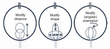
Coupling Loop Matching Strategies
|
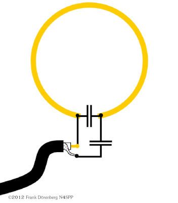
For the case of Magnetic Loop antenna, this matching is typically achieved by usage of a coupling loop. If you look back on Chapter 2 of this series, some of the loop schematics indicates that they are not fed by the feedline directly. Instead, the feed line is connected to a yet smaller loop called “coupling loop”, which in turn generates the magnetic field to induce a large current on the main loop. This coupling through the air achieves the desired impedance transformation.
There are ways to vary the coupling to achieve desired impedance match. The diagram left show but three examples, that can be motor-driven to automate the function. If you look back Chapter 2, I showed that my loop antenna impedance match is achieved by stretching up or pressing down the coupling loop. Just like the “modify shape” example in the diagram.
|
There are other ways to achieve the match, some are simpler and others very complex.
In general, though, especially for light, low power applications, because the impedance match is relatively broad-banded than resonance tuning, it is likely adjusted to one frequency in the band and left alone, sometimes even across multiple bands. Though it is a compromise, most commercial MLA products that work that way.
To operate this type of antenna at the maximum efficiency, it is highly desirable if both resonance and impedance match is performed simultaneously for the frequency of operation.
Dual-Port Automatic Tuner
JR1OAO, Nakajima-san, one of the prominent MLA-48 member, designed and built a super tuner that achieves resonance and impedance match at the same time for the perfect match on his Mag Loop antenna. The unit does not contain LC networks to transform impedance here. Instead, it controls the match mechanism on the antenna itself. It does so by having two motor driver ports to control tuning and matching motors simultaneously. And once the match is achieved, it will re-achieve the match in seconds every time you change the frequency and transmit. I acquired a prototype unit and a ton of design information on it.
The brief block diagram is shown below. |
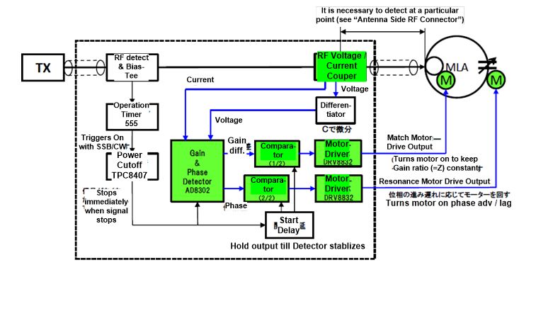 |
It is an amazing, yet very simple design. How he accomplishes the task needs some detailed discussion.
So, the story continues…
Meanwhile, bring those comments, questions, suggestions to me: tak@w6si.com
To be Continued... |
Resources
Not all of the information I present come from my own research & experiment. In fact (not surprisingly) most came from outside sources, which helped me learn the subject in relatively short time and still learning. Some of the most valuable information come from sources below.
With appreciation and gratitude, may I present:
AA5TB
Mr. Steve Yates publishes a lot of precious information about small loop antenna. Many are very useful and practical, with a good deal of theory behind it. And lots of useful links.
http://www.aa5tb.com/loop.html
…and not the least of it is his small loop calculator!
http://www.aa5tb.com/aa5tb_loop_v1.22a.xls
This is an Excel spreadsheet that by giving a size of the loop and target frequency, it can tell you all about that antenna.
MLA-48 Project
As I mentioned above, this is a Japanese group of scientists, engineers, builders and enthusiasts of small loop antennas. The group is led by Dr. Kogure / JG1UNE and Mr. Togoshi JF1VNR. The membership include engineers and hands-on experimenters that amassed amazing quality and volume of information on many aspects of the small antenna. Though many of it is not released publicly, and many of you can’t read them anyway, short of learning an arcane Asian language. since I joined the group recently, with a proper permission, I can “leak” some of the good information on this page (http://w6si.com).
VK5KLT
Since Australia has high concentration of population in the coastal area, the antenna space, apparently is hard to come by, so MLA is pretty popular. The paper published by Mr. Leigh Turner, VK5KLT is a very good thesis on the subject, and a must-read material for those interested. And you thought I was bullish about this antenna. Wait till you read this.
Download it from
http://www.ahars.com.au/uploads/1/3/9/8/13982788/article-antenna-mag-loop-2.pdf
|
|
|
| |
| |
|
|
|